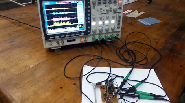
Obtaining Electromyography (EMG) signals from muscles can be challenging. The EMG signal amplitude typically varies between 50 µV and 30 mV, which requires amplifiers with high gain for accurate signal amplification. Due to the ultra-low voltage range of the input signals, significant noise can be introduced during amplification. To address this, a series of filters are used with cutoff frequencies between 0 Hz and 500 Hz, aligning with the typical frequency range of EMG signals. The process of obtaining EMG signals from muscles involves several steps.
Electrodes
Copper (Cu) is a conductive and readily available material, making it a suitable choice for constructing electrodes. The quality of the signal depends on the electrode’s shape and its contact area with the skin. Research on surface electrodes indicates that circular shapes are ideal, with an optimal diameter of 10 mm for effective signal capture.Filters and Amplifiers
Three electrodes are used to obtain EMG signals. One electrode, placed on a non-muscular part of the body, serves as the reference (ground/passive electrode) and is connected to the ground terminal. The other two electrodes (active electrodes) are positioned on the muscle, with one placed at the muscle’s midpoint and the other near the edge. In this experiment, the target muscle is the calf.
Initially, high-frequency components are filtered out before the signal reaches the differential amplifier. To maintain high input impedance and stable gain, an instrumentation amplifier is used. In the first stage, a low-pass passive filter with a 486 Hz cutoff frequency is applied to each active electrode’s input to ensure that input impedance is maintained. The second stage uses the instrumentation amplifier configured as a high-pass filter with a 16 Hz cutoff frequency, as frequencies below this threshold do not significantly affect the output signal.
Initially, high-frequency components are filtered out before the signal reaches the differential amplifier. To maintain high input impedance and stable gain, an instrumentation amplifier is used. In the first stage, a low-pass passive filter with a 486 Hz cutoff frequency is applied to each active electrode’s input to ensure that input impedance is maintained. The second stage uses the instrumentation amplifier configured as a high-pass filter with a 16 Hz cutoff frequency, as frequencies below this threshold do not significantly affect the output signal.
The circuit’s behavior depends on its frequency response, as shown in the simulated frequency response graph below.
According to the frequency response curve, the circuit functions as a band-pass filter, with approximately 16 Hz as the lower cutoff frequency and 500 Hz as the upper cutoff frequency. The prototype circuit, which includes additional components such as a notch filter, gain amplifier, rectification circuit, and pass filters, is shown below.
The instrumentation amplifier used in this circuit is the INA128, which is known for its high common-mode rejection ratio (CMRR) of 120 dB. Shown below is the EMG signal output during calf muscle contraction and relaxation, displaying both the time-domain waveform (blue) and the frequency-domain waveform (red). The 50 Hz power supply frequency is also visible in the output.


